RCC工作原理,附英文版本讲解(直流电源工程师必懂)
RCC变换器通常是指自振式反激变换器。它是由较少的几个器件就可以组成的高效电路,已经广泛用于小功率直流电源电路离线工作状态。由于控制电路能够与少量分立元件一起工作而不会出现差错,所以直流电源电路的总的花费要比普通的PWM反激逆变器低。一方面,当其控制电流过高时就会出现一种间歇振荡现象,从而使得直流电源电路的振荡周期在很大范围内变化,类如例如从数百赫兹到数千赫兹之间变化,因而在较大功率输出时将引起变压器等产生异常的噪音,所以需要抑制这种现象的产生。另一方面,当直流电源电路的输出功率输出较小时,却可以利用这种间歇振荡,使开关电路处于低能耗状态。当需要直流电源电路工作时,只需给电路一个信号脉冲即可。
最近无意看到一些推送的直流电源RCC原理讲解,文章大多从网上转载,内容真实性不说,原理讲解也很勉强,本人尝试把所学与各位分享。
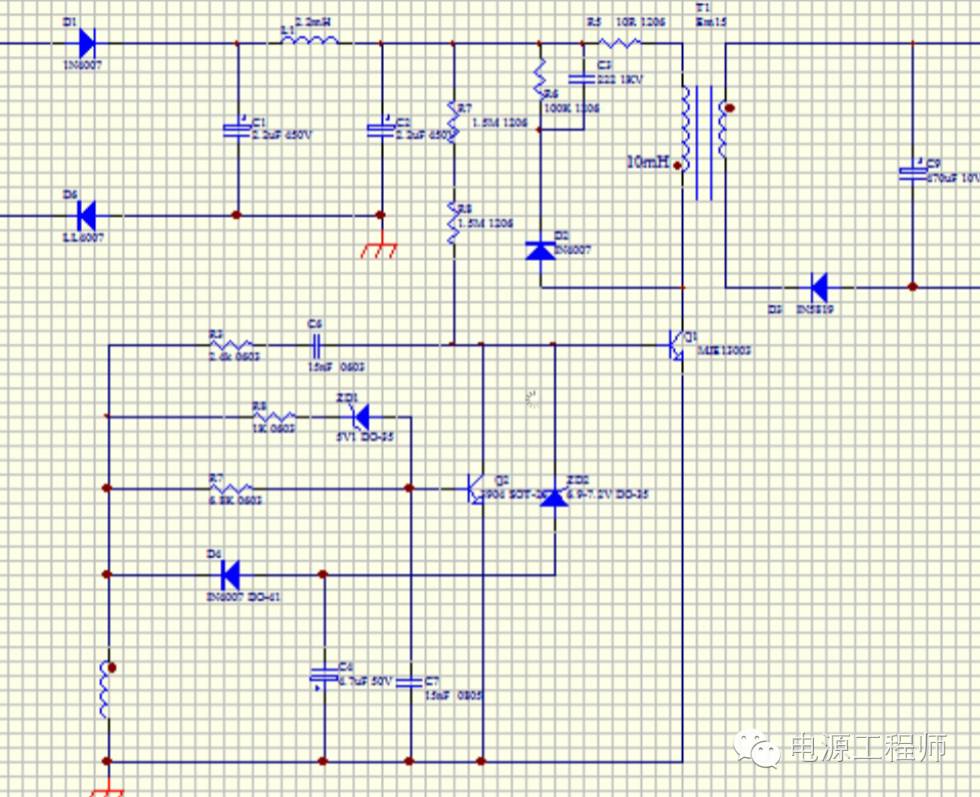
如下为一款量产过百万的RCC电路,虽然现在RCC电路采用者相对较少,但是作为直流电源研发精英,如果讲不清RCC工作原理,未免是一种遗憾。

如上是一款经典的RCC直流电源应用图,输出功率为2W左右,这是一个改良过的RCC电路,直流电源可以做到恒流,恒压的输出,无需光耦,不输于一般的PSR芯片,应用可以称得上绝妙!
RCC是一种自激式震荡电路,直流电源电路简单,可靠,其拓扑原理等同反激式电路拓扑,变压器的设计等同反激式,此文不再讨论。
本文中讲述RCC如何自激的过程,以及直流电源如何实现恒流恒压。

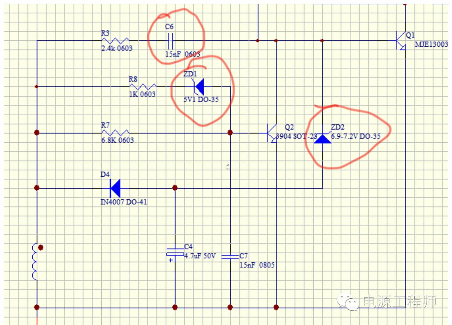
如上图,将整个原理图局部放大,我们从RCC启动开始讲解:
直流电源上电后,Q1的B极从两颗启动电阻(分别1.5M)得到启动电流,Q1三极管开始 导通。启动电阻应尽量大,直流电源将启动电流维持在1MA以上即可,降低待机功耗。
Q1导通后,辅助绕组得到感应电压,感应电压通过向C6充电,然后驱动三极管的B极,加速Q1导通。
搞清楚Q1三极管如何截止是理解RCC自激的关键。C6获取充电后,对Q1的B极放电,Q1的Ic在瞬间是逐步线性增加,同时Ib是逐步减小的,Q1的Ice逐步增加到Ic=Ib*B(beta)时,其实可以理解成Ib电流减小到不足以支撑Ic这个点时,Q1三极管Vce开始增加,即开始截止,此时Lp上的电压减小,同步辅助绕组电压也减小,辅助绕组最终形成的负压可以稳定的将Q1截止。Q1截止期间,次级绕组开始放电,直到电量放完,Q1又开始启动打开的循环。
C6的作用,是控制Q1开关的关键,但不是自激震荡的电路部分。C6值的大小,可以决定Q1三极管导通的时间,电源起机能力。
该直流电源电路电压和电流的稳定,主要通过Q2和ZD1组成的负反馈控制,ZD1的电压为5.1V,所以直流电源的输出电压也会钳位在5V 左右(因为有R8),当输出电压过高时,电压会击穿ZD1,从而导致Q2导通,从而降低Q1的IC电流,达到控制输出电压的目的。ZD2的作用主要是做高压补偿,当交流输入过高后,ZD2同样形成负反馈的作用,限制电源的输出功率。
如有兴趣探讨具体计算过程,可以关注本公众号参与直流电源工程师讨论群讨论。
英文好的同学,可以看看老外的解释:
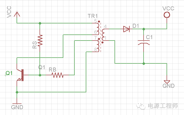
一、直流电源RCC工作原理图RCC基本模型:

Components in Circuit:
1. TR1: three windings SMPS Transformer:
Primary winding (PRI): 5-6,
Secondary winding (SEC): 1-4,
Auxiliary winding (AUX): 7-8
2. Q1: switching power transistor
3. RS: resistor for start-up current
4. RB: resistor to limit the base current of Q1
Working process
Q1 transistor acts as a switch in circuit, it is off at the beginning,
When the power is applied on the circuit, a small start-up current will flow through RS resistor into the base pin of Q1, the Q1 is partially on.
Then, the PRI winding (5-6) gets positive voltage difference (Vin – Vce), and the AUX winding (7-8) also gets same polarity positive voltage, this AUX winding voltage will generate current flowing through RB resistor into the base pin of Q1, so the base current increases , and Q1 turns on more.
It is positive feedback process, the Q1 will be fully on quickly.
As Ip=Vp/Lp * t, the current in PRI winding (5-6) path begins increasing linearly, and Ip will reach the critical point finally – Ip=Ib*B (beta), beyond this point, according to transistor characteristic curves,
A little Ic (equals to Ip here) increasing will cause a bigger Vce increasing, this means the Q1 will leave saturation region, and Vce will increase dramatically.
Therefore, the voltage on PRI winding will begin to decrease, the voltage on AUX winding will decrease too, this will make transistor base current decreasing, it is positive feedback process again, and will lead to transistor turn-off quickly.
When transistor is off, the AUX winding will get negative voltage, and draw the current from Q1 base to keep it off firmly.
The SEC winding (1-4) will get polarity reversed voltage, D1 diode becomes conducted and energy stored on PRI winding transfers to SEC winding, then to load.
After all stored energy is released, the current on every winding is zero, and voltage on every winding is zero too, then this cycle starts again.
Notes
1. This circuit doesn’t regulate output voltage
2. RCC SMPS works exactly at the point between continuous mode and non-continuous mode
3. The cycle frequency depends on B (beta) value of transistor which is not reliable
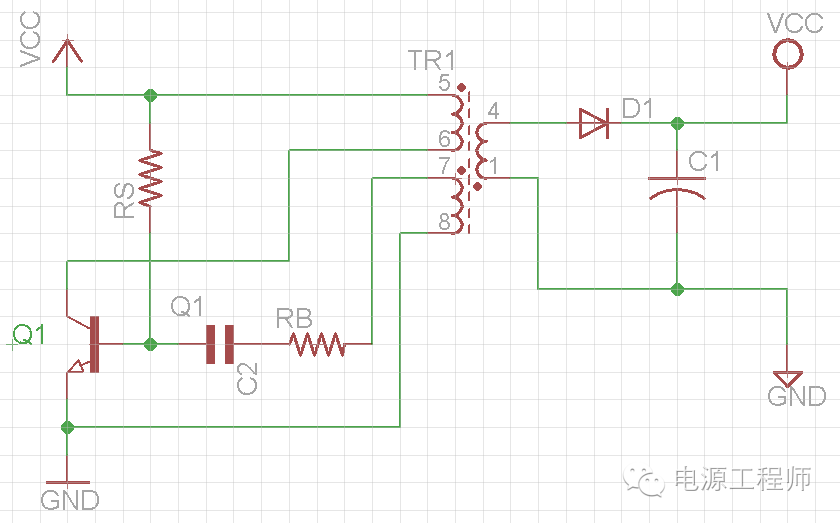
二、直流电源RCC工作原理图改良电路

Function of capacitor C2
Let’s start from the point when Q1 is fully on , then C2 begins to charge according to RC time constant curve, at same time the current in PRI winding will increase linearly and energy is stored.
As C2 keeps charging, the voltage on resistor RB will decrease, and the current to Q1 base will decrease too.
So Ip keeps increasing and Ib keeps decreasing, then a critical point will be reached where Ip=Ib * B (beta), after that, the Ib keeps decreasing, then the Vce will increase, this means the voltage on PRI winding will decrease, and the voltage on AUX winding will also decrease, this will speed up Ib decreasing, and finally turn off Q1,
After Q1 turns off, the PRI winding will get a reversed voltage, so does AUX winding, this will draw away current from Q1 base, and C2 begins to discharging, the energy stored on PRI winding begins to release to load through SEC winding,
After all stored energy is released, the circuit returns to starting point, and the cycle will repeat all over again.
Notes
a. It is clear here that capacitor C2 can control the cycle-on time and frequency.
According to RC time constant curve, small value capacitor can decrease cycle on time, and provide less power to output every cycle, so circuit will have a higher cycle frequency; a large value capacitor will increase cycle on time, and provide more power to output every cycle, so circuit will have a lower cycle frequency
b. Relation between Load and Frequency:
Heavy load => less cycle off time (larger duty cycle) => higher frequency
Light load =>more cycle off time (smaller duty cycle) =>lower frequency
- 上一篇:【快速充电】日本加快全固态电池研发 2017/5/26
- 下一篇:【技术前沿】无需电池和充电机,可穿戴设备可实现自生电 2017/5/26
